Description
The VS1(Z N63) indoor AC vacuum circuit breaker (Hereinafter referred to as breaker) is a three-phase AC 50HZ 12KV indoor switchgear, is available for the control and protection purposes for electrical installations of industrial and mining enterprises, power plants and substations, and is suitable for the places that require frequent operation.
The breaker meet the G B1984-89
We adopt the integrated design for the circuit breaker operating mechanism and the circuit breaker body, both can be used as fixed installation unit, and be equipped with a special propulsion mechanism, to form a handcart unit.

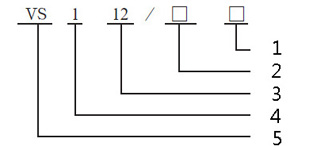
1.Rated short circuit breaking current (KA)
2. Rated current (A)
3. Rated voltage (KV)
4. Product design serial number
5. Vacuum circuit breaker
Environmental Conditions
Normal Conditions of Use
This device is a combinated low-voltage withdrawable switchgear assembled by standard modules, is suitable for power system with AC 50-60Hz and rated working voltage of 660V and below, for the control of power generation, transmission and distribution, power conversion and power consumption devices.
1. Ambient temperature not higher than +40℃, not lower than -15℃ (Allow storage and transport at -30 ℃)
2. Altitude less than 1000m.
3. Relative humidity: Daily average less than 95%, monthly average less than 90%, daily average of saturated vapor pressure less than 2.2×10⁻³MPa, monthly average less than 1.8×10⁻³Mpa.
4. Places without fire, explosion, heavy pollution, chemical corrosion and vibration.
Special Conditions of Use
1. Altitude more than 1000m.
2. Climatic conditions with high humidity or greater humidity mutation, and place with moisture condensation risk.
For special conditions of use, the manufacturer should discuss with user to reach an agreement to provide specialized design and supply.
| No. | Item | Unit | Parameter | ||||
| 1 | Rated voltage | kV | 12 | ||||
| 2 | Rated insulation level | Rated lightning impulse voltage withstand peak | kV | 75 | |||
| Power frequency voltage withstand (1min) | kV | 42 | |||||
| 3 | Rated short circuit breaking current | kA | 20 | 25 | 31.5 | 40 | |
| 4 | Rated current | A | 630 1250 | 630 1250 | 1250 1600 | ||
| 1600 2000 | 2000 2500 | ||||||
| 2500 3150 | 3150 4000 | ||||||
| 5 | Rated thermal current (Valid values) | kA | 20 | 25 | 31.5 | 40 | |
| 6 | Rated dynamic current (Peak value) | kA | 63 | 80 | 100 | ||
| 7 | Rated short-circuit current (Peak value) | kA | 50 | 63 | 80 | 100 | |
| 8 | Breaking times of rated short circuit breaking current | Times | 50 | ||||
| 9 | Secondary circuit power frequency voltage withstand (1min) | V | 2000 | ||||
| 10 | Rated operating sequence | O-0.3S-CO-180S-CO O-180S-CO-180S-CO | |||||
| 11 | Rated thermal stabilization time | S | 4 | ||||
| 12 | Rated single / back to back capacitor bank breaking current | A | 630/400 800/400 (40kA) | ||||
| 13 | Mechanical life | Times | 10000 | ||||
| No. | Item | Unit | Parameter | |
| 1 | Contact opening distance | mm | 10±1 | |
| 2 | Contact stroke | mm | 3.5±0.5 | |
| 3 | Average closing speed (6mm ~ Contact closure) | m/s | 0.8±0.2 | |
| 4 | Average opening speed (Contact closure ~ 6mm ) | m/s | 1.1±0.2 | |
| 5 | Opening time (Rated voltage) | ms | 20-60 | |
| 6 | Closing time (Rated voltage) | ms | 25-60 | |
| 7 | Contact closing bounce time | ms | ≤2 | ≤3 (40kA) |
| 8 | Different period of three-phase opening | ms | ≤2 | |
| 9 | Allowed cumulative wear thickness of dynamic and static contact | mm | 3 | |
| 10 | Electrical loop resistance | μΩ | ≤50(630A) ≤45(1250A) ≤35(1600 ~ 2000A ) ≤25(more than 2500A) | |
| 11 | Contact pressure of closing contacts | N | 2000±200(20kA) 2400±200(25kA) 3100±200(31.5kA) 4500±250(40kA) | |
| Item | Rated voltage ( V ) | Rated input power (W) | Normal operating voltage range (V) | Energy storage time under rated voltage (S) |
| ZYJ55-1 | DC110 DC220 | 70 | 85% ~ 110% rated voltage | ≤15 |


